Analytical study of the fractional reduction in the field enhancement factor of identical rectangular emitters during depolarization Edgar Marcelino de Carvalho Neto*
Department of Physics, Federal University of Minas Gerais, Belo Horizonte, Minas Gerais, Brazil
*Correspondence to: Edgar Marcelino de Carvalho Neto
Citation: De Carvalho Neto EM (2021) Analytical study of the fractional reduction in the field enhancement factor of identical rectangular emitters during depolarization. Sci Academique 2(1): 43-49.
Received: 23 March, 2021; Accepted: 23 April 2021; Published: 29 April 2021
Abstract: The Schwarz-Christoffel transformation is used to analytically evaluate the Field Enhancement Factor (FEF) in the vicinity of the upper corner of two infinite rectangular emitters close to each other. It is showed that the fractional reduction between the apex-FEF of a single emitter and this same FEF evaluated when another identical emitter is placed close to it, −δ, may be well described by an exponential or a power-law behaviour involving the ratio between the distance of the emitters to each other and their heights. This way the analytical model presented here intends to investigate the existence of universal depolarization laws for emitters used in different scientific and technological applications involving Large Area Field Emitters (LAFEs).
Introduction
Field emission [1–4] generally plays an essential role as a mechanism of electron generation in vaccuum electronic technology, being an active topic of research [5–7] of fundamental importance to different scientific and technological applications [8–12]. This happens due to the many advantages of field emission cathodes over the thermionic ones, avoiding issues related to temperature operation and temporal response. For these reasons, it is expected that the next generation of high performance field emission systems, to be used in vaccuum technological applications, will be based on field emission [13, 14]. In particular, Large Area Field Emitters (LAFEs) are of great interest to many different technological applications related to vacuum nano-electronic devices, such as: high-brightness electron sources [5], high power microwave vacuum devices [15] and x-ray generators [16]. Most of these applications involve the use of carbon nanotubes [7, 17, 18]. LAFEs are frequently characterized by their capability to amplify an externally applied electrostatic field, which is essential to achieve a good field emission performance. This capability may be expressed by means of the concept of local Field Enhancement Factor (FEF), consisting of the ratio between the absolute values of the electrostatic field at some point on the surface of the emitter, E, and the electrostatic applied field far away from the emitter, E0:

The FEF on the apexes of the emitter’s sites of a LAFE may be obtained through a Fowler-Nordheim plot [19], if the emission is orthodox [20], when the LAFE consists of emitters with regular apexes and similar shapes. Theoretical and phenomenological studies estimating FEF values or their qualitative behave in LAFEs or for Single Tip Field Emitters (STFEs) are also frequent in the literature concerning field emission [21–29]
In a LAFE the FEF on the apexes of the emitter’s sites tends to be smaller, compared to the case of a single emitter, due to the electrostatic repulsion between the charge densities on each site. For this reason the FEF decreases as different sites become closer to each other, forming a cluster. This phenomenon is well known in the literature as screening, shielding or depolarization [22, 30–36] and plays a major role in applications involving LAFEs. The screening is responsible for higher FEF values in the borders, providing a non-uniform emission along the LAFE [30]. As expected, as the spacing between the emitter’s sites in a LAFE increases, the FEF on the apex of each site tends to increase and asymptoticaly converge to the FEF of a single site for large distances. Different surveys in the literature suggest that some universal laws may provide a good approximation for the fractional reduction of the apex FEF both for short distances, comparable to the dimensions of the emitter, and for large distances. The fractional reduction, −δ, is defined by the following equation

where γ is the apex FEF of the site in a LAFE or in the case of two emitters and γ 1 is the same FEF evaluated when only a single emitter site is present. Considering the Hemisphere over Cylindrical Post (HCP) model, some works [37, 38] suggest that when the distance between emitters, d, is from the same order of their heights, h, the fractional reduction may be well approximated by an exponential law:

with A = 1 and B ≈ 2.3172. A work using line-charge model [39] for post emitters finds a better fitting generalizing Eq. (3) to

with A = 1. On the other hand, for a large distance between the emitters and considering a simplified version of the HCP model, Ref. [34] suggests that the fractional reduction obeys a power-law:

with A = 2 and where l corresponds to the height of the cylinder, R to the radius of the cylinder and the hemisphere and d is the distance between the emitters. Thus, h = l+R corresponds to the height of the emitters. This cubic law has also been found in other works in the literature [40–42].
The present survey investigates the robustness of these laws by testing their validity in a particular two dimensional system, which is amenable to an analytical treatment by means of the conformal mapping technique, frequently used in the literature of field emission [26–28, 33, 36]. More specifically, it is considered a system of two rectangular emitters with infinite length and height h at a distance d from each other, see Fig. 1. The electrostatic shielding in this system has already been studied in Ref. [33] by means of FEF evaluation along the emitter but the validity of the aforementioned laws for the fractional reduction was not investigated there. In the present work, the fractional reduction of the FEF close to the upper corner of each emitter in Fig. 1 is evaluated by means of the Schwarz-Christoffel transformation [43, 44] and the validity of the aforementioned laws for the fractional reduction is assessed.
At this point it is important to stress that this survey does not intend to predict FEF values for real three dimensional emitters, since conformal mapping techniques only work in two dimensions. Nevertheless, it is expected that some qualitative aspects in the three dimensional scenario may be investigated and well understood in two dimensions. For instance, it is possible to investigate if the laws given by Eq. (3) and Eq. (5) remain valid in the absence of radial symmetry, which is the case of the emitter showed in Fig. 1. This is the purpose of this article.
In the next section part of the calculations outlined in Ref. [33] is reviewed and the FEF close to the upper corner of the emitter in Fig. 1 is evaluated by means of the Schwarz-Christoffel transformation, than the same evaluation is performed when only a single emitter is present, in the absence of shielding. In Sec. III the plots of the FEF and the corresponding fractional reduction are showed and the fitting to the aforementioned laws is assessed. In the last section the conclusions and perspectives of this manuscript are presented.

Figure 1: The conducting system in the z-plane (z = x + iy) consisting of two rectangular emitters of height h and infinite length. The distance between the emitters is d
A Brief Review of the Model and FEF Evaluation
In the this section the FEF on the right upper corner of the emitter showed in Fig. 1 is evaluated by means of the Schwarz-Christoffel transformation. Than the same evaluation is performed when only a single emitter is present.
A. The characteristic FEF of two rectangular emitters with infinite length

Figure 2: Pre-image in the complex w-plane (w = u + iv) of the emitter showed in Fig. 1. The points A, B, B’, C and C are mapped to the points with the same labels in Fig. 1
The Schwarz-Christoffel transformation mapping the real axis in the w-plane, see Fig. 2, to the polygonal line in Fig. 1 is given by the following expression:

where the following correspondences are fulfilled: z(w =0) = 0, z(w = ±u) = ±d/2 and z(w = ±1) = ± d/2 + ih. The transformation was chosen to be symmetric around the imaginary axis, justifying the first correspondence. Thus, according to Riemann Mapping Theorem [45], it remains for two pre-images to be chosen, one is given by the last correspondence, w = 1, and the other is the preimage of infinity at infinity. The pre-image w = u should be determined from the respective correspondence. The first correspondence determines B = 0 and the other correspondences lead to the following equations:
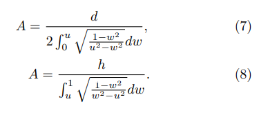
These equations may be combined to determine u as a solution of the following equation:

The FEF at some point in the z-plane, image of a point w = u + iv in the w-plane, is given by

Thus, in the vicinity of the upper corner in the right side of the emitter (z → d/2 + ih ⇒ w → 1), one obtains:

Still in the vicinity of the same corner, Eq. (6) leads to

By combining the last pair of equations and using Eq.(7), it is possible to find the expression of the FEF at some point (x, y) in the vicinity of the aforementioned corner (d/2, h):

where ξ(x, y) is the distance from the corner to the point (x, y) where the FEF is evaluated:

and u is obtained from Eq. (9).
B. The characteristic FEF of a single rectangular emitter with infinite length
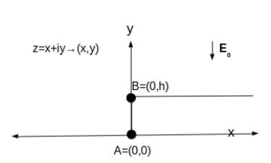
Figure 3: The conducting system in the z-plane (z = x + iy) consisting of a single rectangular emitter of height h and infinite length.
The Schwarz-Christoffel transformation mapping the real axis in the w-plane, see Fig. 4, to the polygonal line in Fig. 3 is given by the following expression:

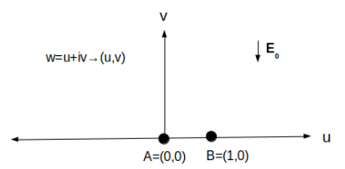
Figure 4: Pre-image in the complex w-plane (w = u+iv) of the emitter showed in Fig. 3. The points A and B are mapped to the points with the same labels in Fig. 3.
where the correspondences z(w = 0) = 0 and z(w = 1) = ih are chosen based on the Riemann Mapping Theorem [45]. The first of these correspondences allows to determine the parameter B, than the second one allows to find A:

The FEF at some point in the z-plane in Fig. 3, image of a point w = u + iv in the w-plane in Fig. 4, is given by

Thus, close to upper corner in Fig. 3 (w → 1), Eq. (15) and Eq. (18) lead to

Finally, by combining the last pair of equations, one obtains:


to the distance from the point (x, y), where the FEF is evaluated, to the upper corner in Fig. 3. Eq. (13) and Eq. (21), with u obtained as a solution from Eq. (9), allow to determine the fractional reduction by means of Eq. (2).
Results
As mentioned in the end of the last section, Eq. (2), Eq. (9), Eq. (13) and Eq. (21) allow to determine the FEF and the fractional reduction near the right upper corner of the emitter in Fig. 1. In this section these quantities will be plotted as a function of the ratio involving the distance between the emitters and their heights (d/h). Than the logarithm of the fractional reduction will be plotted as a function of d/h and log(d/h) in order to show whether the laws given by Eq. (3) and Eq. (5) provide a good description of the fractional reduction at different regimes. The Napierian logarithms will simply be denoted by ”log” (the base is omitted) along the present manuscript.
In Fig. 5 the FEF in the vicinity of the point C in Fig. 1 is showed. As expected, the FEF increases as long as the ratio d/h increases due to the reduction of the shielding. The dashed line shows this same FEF when only a single emitter is present, as showed in Fig. 3. One can see that for very large distances between the emitters the FEF tends to the one in the case of a single emitter, showing the consistency of the evaluation performed in the present survey. In Fig. 6 the fractional reduction of the FEF close to the right upper corner of the emitter in Fig. 1 is showed. The fractional reduction decreases monotonically with the distance between the emitters due to shielding and tends to zero for very large distances, showing the same consistency of the calculations discussed in Fig. 5.
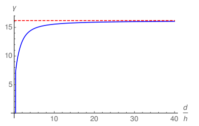
Figure 5: FEF in the vicinity of the right upper corner of the emitter in Fig. 1 for ξ(x, y) = 0.0001. The (red) dashed line corresponds to the same FEF (η(x, y) = 0.0001) in the case of a single emitter showed in Fig. 3.
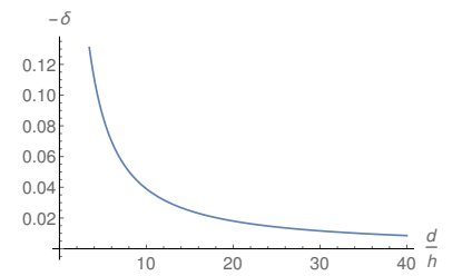
Figure 6: Fractional reduction of the FEF in the vicinity of the right upper corner of the emitter showed in Fig. 1 for ξ(x, y) = η(x, y) = 0.0001.
In Fig. 7 and Fig. 8 the filled lines show the logarithm of the fractional reduction as a function of the ratio d/h. The dashed line in Fig. 8 corresponds to a linearization of the data contained in twenty equidistant points of the filled line in this plot. One can see that, for values of the distance between the emitters close to their heights, the plot is approximately linear. This is easier to see in Fig. 8, reinforcing the validity of Eq. (3) as a reasonable approximation in this regime. Nevertheless, although this linearization is able to provide a good fitting to the fractional reduction, it does not provide a perfect description of the system, showing that the approximation in Eq. (3) is limited
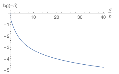
Figure 7: Logarithm of the fractional reduction in the vicinity of the right upper corner of the emitter showed in Fig. 1 as a function of the ratio d/h for ξ(x, y) = η(x, y) = 0.0001.
In Fig. 9 and Fig. 10 the filled lines show the logarithm of the fractional reduction as a function of the logarithm of the ratio d/h. The dashed line in Fig. 10 corresponds to the linearization of twenty equidistant points in the filled line of this plot. One may see that for large values of d/h the plot becomes linear, as it is easier to see in Fig. 10, reinforcing the validity of Eq. (5) for large values of the ratio d/h. Fig. 10 shows that the linearization of the plot in Fig. 9 for large distances is coincident with the original plot, suggesting that Eq. (5) provides a better description of the fractional reduction for large distances than Eq. (3) for small distances and that the fractional reduction for asymptotically large distances between the emitters corresponds indeed to a power-law decay. Although in the three-dimensional scenario this power-law corresponds to a cubic decay [34, 40–42], the exponent of the power-law in the present survey is approximately given by 1.12. This is not surprising since the FEF presents a logarithmic dependence with the curvature of the emitter in two dimensions, which differs from the power-law dependence in the three-dimensional case.
Although the plots and linearizations showed along this manuscript suggest the validity of the aforementioned laws, given by Eq. (3) and Eq. (5), the values of the parameters obtained here blatantly differ from the ones in the literature. This difference is expected, since the models studied here are two-dimensional, as discussed in the last paragraph. This is a limitation of the conformal mapping technique, which only works to evaluate FEFs of ridge emitters. Besides that, it is also important to notice that the other results in the literature discussed along this text concern to emitters with radial symmetry distant to each other, which is not the case of the rectangular cathodes studied here. Moreover, since this manuscript works with emitters with infinity length, it is not possible to test whether the parameters in Eq. (3) and Eq. (5) are universal or change for different values of the aspect-ratio of the emitters, although the universality of the expressions given by Eq. (3) and Eq. (5) is reinforced. This is an interesting future perspective for the present work.
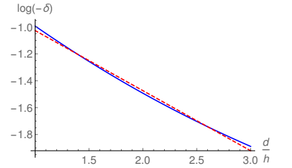
Figure 8: The (blue) filled line represents a restriction of the plot in Fig. 7 for small values of d/h. The (red) dashed line shows a linearization obtained from using 20 equidistant points from the plot in Fig. 7.
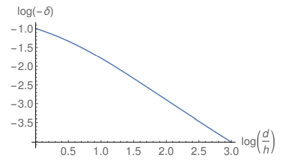
Figure 9: Logarithm of the fractional reduction in the vicinity of the right upper corner of the emitter showed in Fig. 1 as a function of the logarithm of the ratio d/h for ξ(x, y) = η(x, y) = 0.0001.
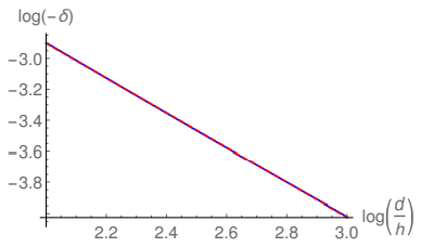
Figure 10: The (blue) filled line represents a restriction of the plot in Fig. 9 for large values of d/h. The (red) dashed line shows a linearization obtained from using 20 equidistant points from the plot in Fig. 9.
Conclusions and Future Perspectives
This present work uses the Schwarz-Christoffel transformation to evaluate the FEF and the fractional reduction in the vicinity of the upper corner of two rectangular emitters with infinite length close to each other. This way it is possible to analytically investigate whether the laws given by Eq. (3) and Eq. (5) are able to provide a good description of the fractional reduction during shielding at short and/or large distances between the emitters.
The results obtained here show that Eq. (5) provides an excellent fitting to the fractional reduction for large distances between the emitters, reinforcing the idea that this quantity fulfills a power-law decay for asymptotically large distances. Eq. (3) seems to provide a reasonable but imperfect fitting to the real curve of the fractional reduction for small distances between the emitters.
As a limitation of the conformal mapping technique, only ridge emitters are described in this survey, which explains the difference between the parameters found here and in the literature. This difference is not surprising, since the logarithm dependence of the FEF with the curvature of the emitter in two dimensions differs considerably from the power-law dependence expected in the three-dimensional scenario. Nevertheless, the simple model studied here is able to investigate whether the exponential or the power-law behave, given by Eq. (3) and Eq. (5) respectively, are able to describe the fractional reduction close to the upper corner of the emitters considered here at different regimes during shielding. Moreover, the validity of Eq. (5) is reinforced even for emitters without radial symmetry.
Future perspectives of the present survey include to apply the Schwarz-Christoffel transformation to study emitters with other geometries and finite length, allowing to investigate the universality of the parameters in Eq. (3), Eq. (4) and Eq. (5) for different aspect-ratios. The simple model studied here using emitters with infinite length was successful to assess the validity of the aforementioned laws but it is not able to assess the universality of the parameters in these laws.
Acknowledgments
This study was financed in part by the Coordination for the Improvement of Higher Education Personnel – Brazil (CAPES) – Finance Code 001.
References
- Jeffreys H (1925) On Certain Approximate Solutions of Linear Differential Equations of the Second Order, Proc.
- Fowler RH, Nordheim L (1928) Electron emission in intense electric fields. Proc. R. Soc. Lond. Ser. A 119: 173-181.
- Burgess RE, Kroemer H, Houston JM (1953) Corrected Values of Fowler-Nordheim Field Emission Functions v(y) and s(y). Phys. Rev. 90: 515-515
- Murphy EL, Good RH (1956) Thermionic Emission, Field Emission, and the Transition Region. Phys. Rev. 102: 1464-1473.
- Jensen KL, Shiffler DA, Petillo JJ, Pan Z, Luginsland JW (2014) Emittance, surface structure, and electron emission. Phys. Rev. ST Accel. Beams 17: 043402.
- Holgate JT, Coppins M (2017) Field-Induced and Thermal Electron Currents from Earthed Spherical Emitters. Phys. Rev. Appl 7: 044019.
- Urban F, Passacantando M, Giubileo F, Lemmo L, Bartolomeo A Di (2018) Transport and Field Emission Properties of MoS2 Bilayers. Nanomaterials 8: 151.
- Cole MT, Mann M, Teo KB, Milne WI (2015) Emerging Nanotechnologies for Manufacturing, Micro and Nano Technologies, 2nd ed., edited by W. Ahmed and M. J. Jackson (William Andrew Publishing, Boston.
- Graves WS, Artner FXK, Moncton DE, Piot P (2012) Intense Superradiant X Rays from a Compact Source Using a Nanocathode Array and Emittance Exchange. Phys. Rev. Lett. 108: 263904.
- Akashi T, Takahashi Y, Tanigaki T, Shimakura T, Kawasaki T, et al. (2015) Aberration corrected 1.2-MV cold field-emission transmission electron microscope with a sub-50-pm resolution. Appl. Phys. Lett. 106: 074101.
- Lewellen JW, Noonan J (2005) Field-emission cathode gating for rf electron guns. Phys. Rev. Spec. Top. Accel. Beams 8: 033502.
- Miller HC (1989) Surface flashover of insulators, IEEE Trans. Electr. Insul. 24: 765-786.
- Teo KBK, Minoux E, Hudanski L, Peauger F, Schnell JP, et al. (2005) Carbon nanotubes as cold cathodes. Nature 437: 968-968.
- Parmee RJ, Collins CM, Milne WI, Cole MT (2015) X-ray generation using carbon nanotubes. NanoConvergence 2: 1.
- Whaley DR, Gannon BM, Smith CR, Armstrong CM, Spindt CA (2000) Application of field emitter arrays to microwave power amplifiers, IEEE Trans. Plasma Sci. 28: 727-747.
- Basu A, Swanwick ME, Fomani AA, Velasquez-Garcıa L F (2015) A portable x-ray source with a nanostructured Pt-coated silicon field emission cathode for absorption imaging of low-Z materials. J. Phys. D: Appl. Phys. 48: 225501.
- Carbon Nanotube and Related Field Emitters, edited by Y. Saito (Wiley-VCH, Weinheim, 2010)
- Li Y, Sun Y, Yeow JTW (2015) Nanotube field elec[1]tron emission: principles, development, and applications. Nanotechnology 26: 242001.
- Forbes RG, Deane JHB, Fischer A, Mousa MS (2015) Fowler-Nordheim Plot Analysis: A Progress Report. Jordan J. Phys. 8: 125-147.
- Forbes RG (2013) Development of a simplequantitative test for lack offield emission orthodoxy, Proc. R. Soc. London A 469: 20130271.
- de Assis T A, Dall’Agnol FF (2017) Trade-off between the electrostatic efficiency and mechanical stability of two-stage field emitter structures. J. Appl. Phys. 121: 014503.
- DallAgnol FF, de Assis TA (2017) Close proximity electrostatic effect from small clusters of emitters. J. Phys.: Condens. Matter 29: 40LT01.
- Jensen KL, Shiffler DA, Harris JR, Petillo JJ (2016) Schottky’s conjecture, field emitters, and the point charge model. AIP Adv. 6: 065005.
- Harris JR, Jensen KL (2019) Verifications of Schottky’s Conjecture. J. Appl. Phys. 125: 215306.
- Harris JR, Shiffler DA, Jensen KL, Lewellen JW (2019) Investigation of the Schottky Conjecture for compound structures modeled with line charges. J. Appl. Phys. 125: 215307.
- Miller R, Lau YY, Booske JH (2007) Electric field distribution on knife-edge field emitters. Appl. Phys. Lett. 91: 074105.
- Miller R, Lau YY, Booske JH (2009) Schottky’s conjecture on multiplication of field enhancement factors. J. Appl. Phys. 106: 104903.
- Marcelino E, de Assis TA, de Castilho CMC (2017) Unexpected validity of Schottky’s conjecture for two-stage field emitters: A response via Schwarz Christoffel transformation. J. Vac. Sci. Technol. B 35: 051801.
- Marcelino E, de Assis TA, de Castilho CMC, Andrade RFS (2019) First-Principles Analysis of Nano electromechanical Systems Using the Loewner Equation. Phys. Rev. Appl. 11: 014012.
- Harris JR, Jensen KL, Shiffler DA (2016) Edge enhancement control in linear arrays of ungated field emitters. J. Appl. Phys. 119: 043301
- Harris JR, Jensen KL, Shiffler DA (2015) Modelling field emitter arrays using line charge distributions. J. Phys. D: Appl. Phys. 48: 385203.
- Harris JR, Jensen KL, Shiffler DA, Petillo JJ (2015) Shielding in ungated field emitter arrays. Appl. Phys. Lett. 106: 201603.
- Tang WW, Shiffler DA, Cartright KL (2011) Analysis of electric field screening by the proximity of two knifeedge field emitters. J. Appl. Phys. 110: 034905
- Forbes RG (2016) Physical electrostatics of small field emitter arrays/clusters. J. Appl. Phys. 120: 054302.
- de Souza AS, de Assis TA (2020) A classical first principles study of depolarization effects in small clusters of field emitters. J. Appl. Phys. 127: 045304.
- Marcelino E, de Assis TA, de Castilho CMC (2019) Interplay between morphological and shielding effects in field emission via Schwarz-Christoffel transformation. J. Appl. Phys. 123: 124302
- Bonard JM, Weiss N, Kind H, Stockli T, Forro L, et al. (2001) Tuning the Field Emission Properties of Patterned Carbon Nanotube Films. Adv. Mater. 13: 184-188.
- Jo SH, Tu Y, Huang ZP, Carnahan DL, Wang DZ, Ren ZF (2003) Effect of length and spacing of vertically aligned carbon nanotubes on field emission properties. Appl. Phys. Lett. 82: 3520-3522.
- Harris JR, Jensen KL, Shiffler DA (2015) Dependence of optimal spacing on applied field in ungated field emitter arrays. AIP Adv. 5: 087182.
- Dall’Agnol FF, de Assis TA, Forbes RG (2018) Physics-based derivation of a formula for the mutual depolarization of two post-like field emitters. J. Phys Condens Matter 30: 375703.
- de Assis TA, Dall’Agnol FF (2018) Evidence of universal inverse-third power law for the shielding-induced fractional decrease in apex field enhancement factor at large spacings: a response via accurate Laplace-type calculations. J. Phys Condens. Matter 30: 195301.
- Biswas D, Rudra R (2018) Shielding effects in random large area field emitters, the field enhancement factor distribution, and current calculation. Phys. Plasmas 25: 083105.
- Brown J, Churchill R (2013) Complex Variables and Applications, Brown and Churchill Series (McGraw-Hill Higher Education).
- Hildebrand F (1962) Advanced Calculus for Applications. Prentice-Hall.
- Riemann B (1851) Grundlagen fur Eine Allgemeine Theorie fer Functionen Einer Ver¨anderlichen Complexen Grosse, University of Gottingen.


